icwbmx
New member
- Joined
- May 10, 2005
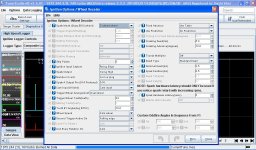
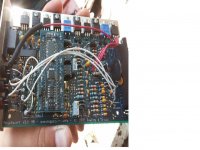
I just added the ms3x board to my ms3. Now the crank signal goes to the main board through the VR circuit and the cam goes to the ms3x board. In addition I'm using ms3x spark outputs to trigger 2 externally mounted coil drivers. Running wasted spark with Josh's hi-res disc.
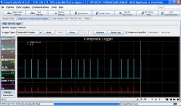
The problem is now the car is not starting. Coil A fires just fine when it's supposed to. It seems though that coil B is only firing once per engine cylcle. Slow-mo video via iPhone brought me to this conclusion.
Could this be just a vr-pot adjustment issue?
Thanks
Ian
The problem is now the car is not starting. Coil A fires just fine when it's supposed to. It seems though that coil B is only firing once per engine cylcle. Slow-mo video via iPhone brought me to this conclusion.
Could this be just a vr-pot adjustment issue?
Thanks
Ian